The Jenkins “Execution Queue” contains all the graphs that are waiting to be executed at a given moment in time. There are, basically, two different ways to “fill-in” the Jenkins “Execution Queue”:
1.Through Jenkins: For example, you can configure Jenkins to execute an Anatella graph X everyday at midnight (see section 4.8.4. for more information about “scheduling” graphs). This means that, everyday at midnight, Jenkins automatically adds the Anatella graph X inside the “Execution Queue” (so that it is executed as soon as possible).
2.Through Anatella: The ![]() “Loop Jenkins” Action (see section 5.21.1) instantaneously adds many Anatella graphs inside the Jenkins “Execution Queue”.
“Loop Jenkins” Action (see section 5.21.1) instantaneously adds many Anatella graphs inside the Jenkins “Execution Queue”.
All the Anatella graphs that are inside the Jenkins “Execution Queue” are executed as soon as possible using all the computing power available inside all the computers managed by Jenkins.
![]()
In technical terms, a server where Jenkins is installed & running (and that is thus able to execute some Anatella graphs) is called a “node”.
Jenkins has several options that allows you to configure exactly what’s the available “computing power”. More precisely:
•You can add/remove “nodes”.
•For each “node”, you can decide the maximum number of graphs that can be executed simultaneously.
1. To Add/Remove “nodes”
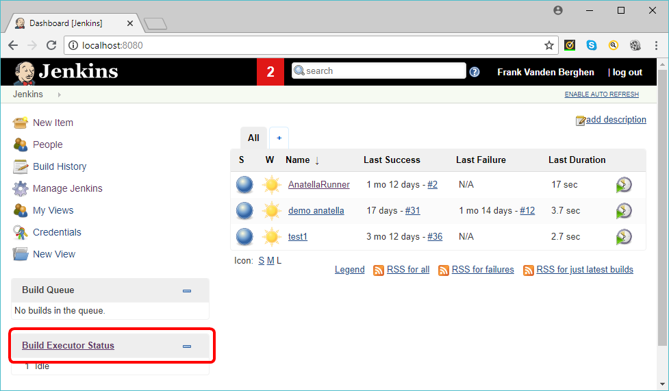
1.1.Open a browser and click on “Build Executor Status” link in the bottom left corner of the “Jenkins” home page:
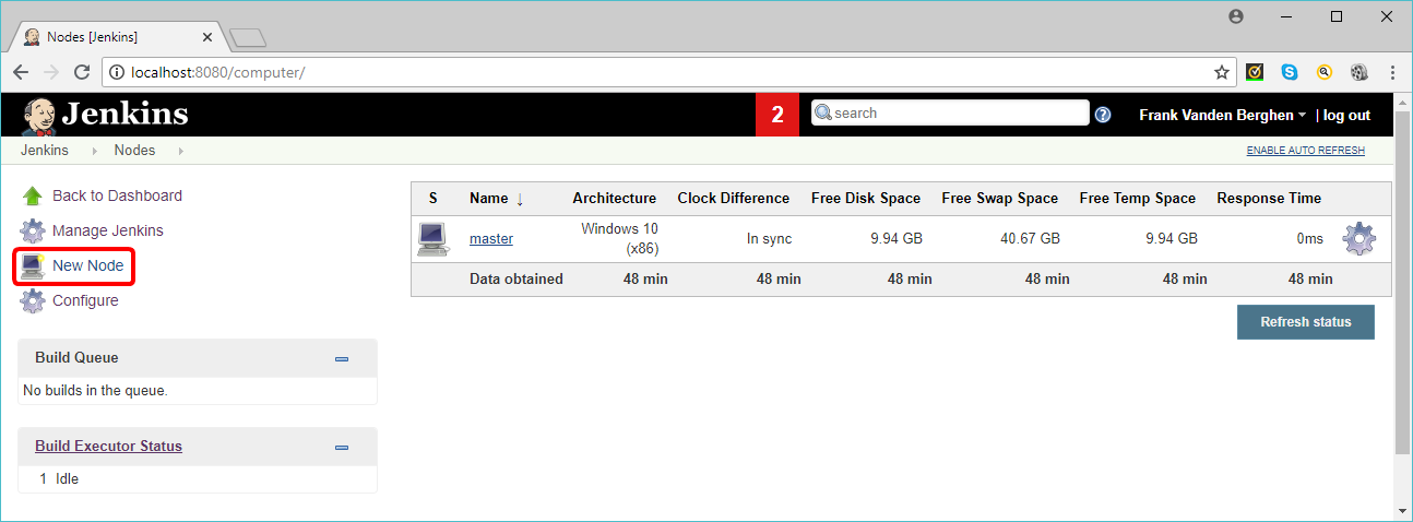
This opens a webpage where you can configure each node managed by Jenkins.
1.2.To add a new computing “Node”, click on the “New Node” link here:
2. To set the maximum number of graphs that will be executed simultaneously on a node
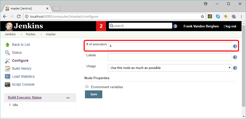
2.1. Click on the node that you want to configure. For example, if you want to configure the “master” node, click in the gear icon, here:
2.2.The maximum number of Anatella graphs that will be executed simultaneously on the “master” node (i.e. the “number of executors”) is defined here (in the example, it’s “4”):
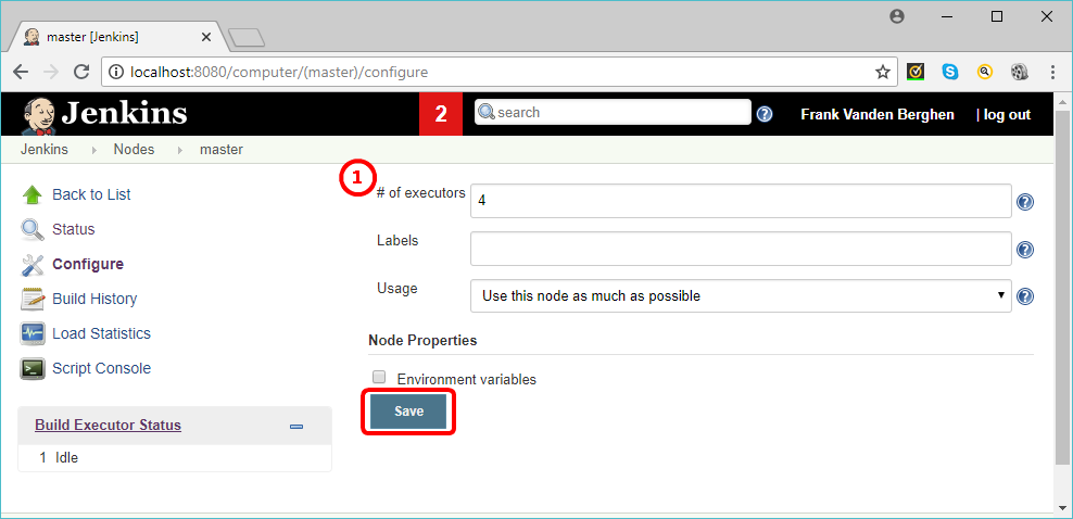
2.3.Click on the “Save” button:
![]()
A good value for the “number of executors” (here: ![]() ) would be the number of CPU cores on the machine. Setting a higher value will cause each graph to take a longer time to execute, but could increase the overall throughput. For example, one graph might be CPU-bound, while a second graph running at the same time might be I/O-bound — so the second graph could take advantage of the spare I/O capacity at that moment.
) would be the number of CPU cores on the machine. Setting a higher value will cause each graph to take a longer time to execute, but could increase the overall throughput. For example, one graph might be CPU-bound, while a second graph running at the same time might be I/O-bound — so the second graph could take advantage of the spare I/O capacity at that moment.
![]()
Setting the number of executors to zero (for a node N) will prevent any graphs from being executed on the node N.